Brief Introduction
The standard GB/T 20234.3:2015 is for larger GBT connector and allows for fast charging at up to 250kW, with current of 80A /125A /200A /250A, and voltage of 750-1000V.However, the new update GB/T 20234: 2023 allow charging to 1000A.
Product Features
- The GBT 250A Electric Vehicle Charger Plugs integrated two temperature sensors on DC pins for monitoring the temperature change.
- This GB/T Electric car plug designed for 10,000+ charging cycles.
- Integrated E-lock inside, can lock on the vehicle side charging inlet to prevent accident drop.
- Excellent protection performance, up to IP55 dust and water proof grade.


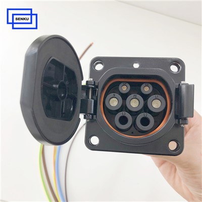
Definition of GB/T Plug
| DC+ | DC Power Supply+ | DC- | DC Power Supply- |
| CC1 | Connect Confirmation | CC2 | Connect Confirmation |
| S+ | CAN-H | S- | CAN-L |
| A+ | 12V+ | A- | 12V- |
| PE | Groudning |

There are four signaling pins in the GB/T 20234.3 Electric Vehicle Charger Plugs: two for confirming charging (CC1/CC2) and two for communication using the CAN bus (S+/S−). Additionally, it provides up to 600W of auxiliary DC power at 30V/20A (A+/A−).
The GBT 250A Electric Vehicle Charger Plugs relies on CAN BUS signaling for control, specifically utilizing the GB/T 27930-2015 protocol, which is based on the SAE J1939 network standard. This differs from the power line communication (PLC) protocol employed by the CCS standard, which evolved from the European Type 2 and North American SAE J1772 (Type 1) AC charging standards.
These signals manage the charging process, including handshake initiation, voltage and amperage configuration, and charging suspension. According to the GB/T 27930-2015 protocol, communication occurs through digital signals over the CAN 2.0B bus at a speed of 250 kbit/sec. Initially, the S+/S- pins establish the communication link, followed by the connection of the A+/A- auxiliary power contacts. The electric vehicle supply equipment (EVSE) sends a handshake signal to the EV's battery management system (BMS) to confirm the S+/S- connection. Once the BMS responds positively, the EVSE performs insulation monitoring and communicates a safety confirmation to the BMS.
When the BMS acknowledges this insulation-safe message, the system moves to the next stage, where charging parameters are exchanged. The BMS sends battery data to the EVSE, which responds with its maximum output. After the BMS confirms this, it evaluates if the vehicle is ready for charging and sends a "BMS ready" message. Once the EVSE confirms its readiness, both systems begin the charging phase. During this stage, the BMS continuously sends battery status updates to the EVSE, which adjusts the current output in real-time, maintaining a feedback loop until a stop-charging message is sent by either the BMS or the EVSE.
What Difference between GB/T 20234.1-2023 and GB/T 20234.1-2015 ?
The national standard GB/T 20234.1-2023 "Connection Devices for Conductive Charging of Electric Vehicles Part 1: General Requirements" for electric vehicle charging piles was officially released on September 7, 2023, and will be implemented on the same day. The new standard not only maintains technical continuity and consistency, but also systematically plans for future development. The new standard has added or changed the following content compared to the old standard in 2015.
1. Interpretation of the New National Standard for Charging Piles GB/T 20234.1-2023
1) Change rated voltage/current:
The rated voltage of the DC connection device has been changed from the original maximum DC 1000V to DC 1500V, and the rated current has been changed from the original maximum DC 400A to DC 1000A.
2) Add some terms and definitions
(1) Simplified schematic diagram of charging connection device;
(2) Adding cable component terminology, the description of equipment on the cable has been expanded compared to GB/T 2015;
(3) Add all content from 3.11 to 3.19, including introductions to locking devices, rated currents, thermal management devices for liquid cooling systems, and gauges;
3. Added testing requirements and methods
(1) It has been clarified that protection level information and current requirements for gun heads with thermal management systems need to be marked on the connection device. The protection level for the terminals and end cavities in the plug has been added to IPX6;
(2) The latest test requirements for the resistance of contacts and terminals to overheating have been added. During high and low temperature resistance tests, two temperature rise tests, safety regulations, and protection level tests are required;
(3) The latest test requirements for the oxidation and overheating resistance of pins and sockets have been added. During the alternating humidity test, two temperature rise tests, insertion and extraction tests, exposure cycles, safety regulations, protection levels, and other tests need to be conducted;
(4) Added nominal cross-sectional area requirements for non grounded conductors and protective grounded conductors;
(5) The cable connection requirements have added testing requirements for liquid medium cooled cable components;
(6) Added requirements for thermal management systems and liquid medium cooling devices: Test items related to the thermal management system of the charging connection device should be tested separately in two states: system closed and open. If the system function cannot be closed, only the system open state should be tested;
(7) Added temperature monitoring function and testing requirements for monitoring function (including liquid cooling);
(8) We have subdivided the testing requirements for various parts of the charging connection device for mechanical strength, and added requirements for components with liquid cooling media;
(9) The requirements for limiting short-circuit current withstand performance testing have subdivided the AC/DC charging connection devices;
(10) After the vehicle compaction test, verification of anti electric shock protection, confirmation of the integrity of the liquid cooling device, and verification of the stress relief of the charging connection device cable were added. Additionally, additional samples were required to repeat the 7.13.1 test under a pressure of 11000N+550N according to the method in 7.13.2, supplementing the testing method for vehicle compaction of charging cables and cable mounted equipment;
(11) Added surface temperature requirements for charging cables;
(12) The overall requirements for the charging connection device have been specified, with separate requirements for the charging interface (including power supply interface and vehicle interface), safety requirements for interface vibration loosening, installation requirements for non insulated live parts of the charging interface, and internal wiring requirements for the interface; It also includes requirements for power socket sockets, vehicle socket drainage holes, coating thickness of interface contacts, prevention of untrained personnel from repairing at the operation station, and the structure of the plug can be grasped;
(13) When the rated current of the AC charging interface is greater than 16A, an electronic locking device needs to be installed. New requirements have been added for the tolerance and service life of the electronic lock, the structure of the locking device after locking, the rigidity requirements of the locking rod, the requirements for the locking rod mechanism of the AC charging vehicle socket, and the additional load requirements for the charging cable under normal working conditions of the DC charging interface;
(14) New requirements have been added for charging interface electrical appliances and components, including that electronic locking devices should be able to withstand storage environment temperatures ranging from -40 ℃ to+85 ℃, with a protection level not lower than IP55;
(15) Regarding the breaking ability, the insertion speed can be reduced according to the manufacturer's requirements, and manual or mechanical insertion and extraction methods can be selected for testing according to the manufacturer's requirements; Unified the number of segmented cycles to 3 times, removed the testing requirements for the breaking capacity of the DC charging interface and the testing parameters for 20A, and added testing parameters for 10A, 125A, and 250A;
(16) The temperature rise has increased the specific location of the measurement points; The temperature rise test parameters have increased the requirements for rated or continuous maximum operating currents of 25A, 50A, 300A, 500A, 600A, 800A, and 1000A, and removed 20A;
(17) The electrical clearance/creepage distance specifies that the control guidance and signal circuits are easily accessible metal components, and if properly protected, they can be considered as low pollution levels internally;
(18) Added requirements for vibration resistance and mechanical impact testing, as well as offset operation requirements; Added durability design and testing requirements for contacts; Added design and testing requirements for charging cables with thermal management systems; Added requirements for cable mounted equipment and corresponding testing methods;
Hot Tags: gbt 250a electric vehicle charger plugs, gbt 250a electric vehicle charger plugs suppliers, manufacturers, factory, gbt ev connector, 32 amp ev charging cable gbt, ev charging station plug 125A, electric car plug standard, gbt public charging cable, gbt ev plug